How do we apply Thevenin’s theorem?
In our previous articles, we discussed various aspects of digital electronics, including things such as logic gates. Now we’re going to look at Thenevin’s theorem and how we can apply it.
What is Thevenin’s theorem?
The theorem is an analytical method that’s used to change a complex circuit into a simple equivalent circuit. It consists of a single resistance in series with a source voltage.
Thevenin’s theorem states that “any linear circuit containing several voltages and resistances can be replaced by just one single voltage in series with a single resistance connected across the load.“.
In other words, it’s possible to simplify any electrical circuit, no matter how complex, to an equivalent two-terminal circuit. This is done with just a single constant voltage source in series with a resistance (or impedance) connected to a load.
Thevenin’s theorem is especially useful in the circuit analysis of power or battery systems and other interconnected resistive circuits where it will have an effect on the adjoining part of the circuit.
Thevenin’s equivalent circuit
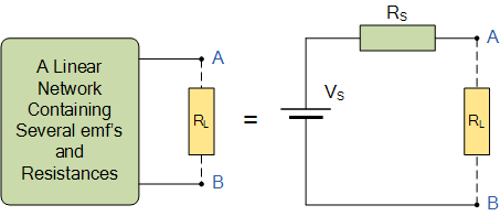
As far as the load resistor RL is concerned, any complex “one-port” network consisting of multiple resistive circuit elements and energy sources can be replaced by one single equivalent resistance Rs and one single equivalent voltage Vs. Rs is the source resistance value looking back into the circuit and Vs is the open circuit voltage at the terminals.
The steps we need to follow when we are solving problems using Thevenin’s theorem are:
- Step 1 : Identify the load (RL).
- Step 2 : Remove the load and calculate the open-circuit voltage (VTH).
- Step 3 : To calculate Thevenin’s impedance (RTH), replace the sources with their internal impedance.
- Step 4 : Construct the Thevenin’s equivalent circuit by connecting (VTH) in series with (RTH).
Solving problems with Thevenin’s theorem.
Let’s have a look at an example to see how we can use Thevenin’s theorem in real life. We’re going to calculate the current through the resistor of resistance 6 Ω. The current is shown in the diagram below:
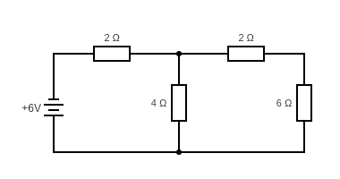
Here the load (RL) = 6 Ω
To calculate Thevenin’s voltage (VTH) :
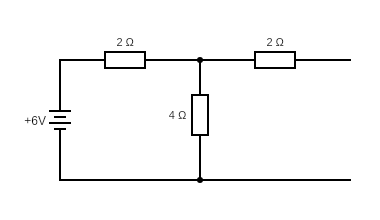
Now we remove the load. When the load is removed, the open-circuit voltage is the same as that of the voltage across the resistor of resistance 4 Ω.
∴ The current in the circuit is

∴ The Thevenin’s voltage is

To calculate Thevenin’s impedance (RTH) :
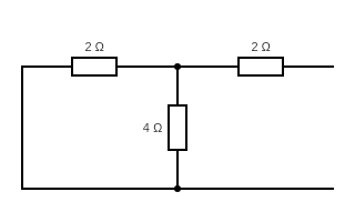
After replacing the source with their internal impedance, Thevenin’s impedance is
![\small R_{TH}=\left [ 2+2\parallel 4 \right ] =\left [ \frac{2\times 4}{2+4}+2 \right ] =\left [ \frac{4}{3}+2 \right ] =\frac{10}{3}\Omega =3.34\Omega , How do we apply Thevenin’s theorem?](https://ilearnengineering.com/wp-content/uploads/2024/05/CE8MC66K-hK6ZgGNyPVtmg964GBxkNyZiU-4CxNPbWbs1babCFCHRuXrWQ5y4qarhYX2ZN00jmb30_XhIMh1jncknGnPYzoIAVi8s2Gd_pj3MQ0g7ra6COBeKwgfjjRyHdNVA78Msx-8S0pwamXLdh0.gif)
Thevenin’s equivalent circuit :
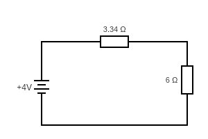
∴ The current through the load,

Keep an eye out for our next articles, where we’re going to shift our focus to Programmable Logic Controller systems.
Interested in our courses?
You can read more about our selection of accredited online electrical and electronic engineering courses here.
Check out individual courses pages below:
Diploma in Electrical and Electronic Engineering
Higher International Certificate in Electrical and Electronic Engineering
Diploma in Electrical Technology
Diploma in Renewable Energy (Electrical)
Higher International Diploma in Electrical and Electronic Engineering
Alternatively, you can view all our online engineering courses here.
Recent Posts
Aircraft Basics: Main Components and Standard Control Surfaces Explained
Aircraft Basics: Main Components and Standard Control Surfaces Explained Introduction In this blog we will identify the main components within an aircraft, more from the point of view of large external parts, more specifically, flight control surfaces. Flight control surfaces are simply physical devices that the pilot can control and adjust in order to change […]
Understanding and Calculating Generator Efficiency and Output Parameters
Understanding and Calculating Generator Efficiency and Output Parameters Introduction The performance of a generator is often judged by how efficiently it converts mechanical energy into electrical energy. Understanding and calculating this efficiency, along with other key output parameters such as voltage, current, power factor, and load, is essential for evaluating performance and ensuring reliable operation. […]
Essential Cooling and Protection Devices: How They Work and Why They Matter
Essential Cooling and Protection Devices: How They Work and Why They Matter Introduction Generators produce a significant amount of heat and electrical stress during operation, which can affect performance and lifespan if not properly managed. That’s where cooling and protection devices come in. These essential systems, including fans, radiators, circuit breakers, and relays, work together […]

