Inside a Generator: The Main Components Explained
Introduction
Electric generators are fascinating machines that turn mechanical energy into electrical power, the very process that keeps our homes, industries, and cities running. But what actually goes on inside a generator? In this article, we’ll take a closer look at the main components that make it work, from the rotor and stator to the voltage regulator and cooling system. Understanding these parts gives you a clearer picture of how generators reliably produce the electricity we depend on every day.
Before we can explain the working principle of a DC generator, we need to cover the basics of generators. Generators (DC and AC) convert mechanical energy into electrical energy based on Faraday’s Law of Electromagnetic Induction. This principle states that an EMF is induced in a conductor when it moves through a magnetic field, cutting magnetic lines of force
The Electromotive Force (EMF) is the measure of the energy per unit charge provided by a source of electrical energy, such as a battery or a generator. It is the driving force that causes electrons to move through a circuit, thereby generating an electric current.
Key Components of a generator are that a Magnetic Field produces magnetic flux and the conductor moves within the magnetic field to generate EMF.
Types of Generators:
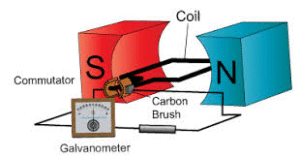
- DC Generator: Produces direct current using a commutator.
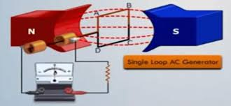
- AC Generator: Produces alternating current naturally without a commutator.
Single Loop DC Generator

A single-loop DC generator operates on the principle of Faraday’s Law of Electromagnetic Induction, where an EMF is induced in a conductor moving through a magnetic field.
Components:
Single Loop Conductor: A rectangular loop of wire.
Magnetic Field: Produced by permanent magnets or electromagnets.
Armature: The rotating part that holds the conductor.
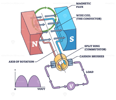
Commutator: A split-ring device that converts alternating EMF into direct current.
Brushes: Stationary components that transfer current from the commutator to the external circuit.
The single loop is placed within the magnetic field, with the two sides of the loop perpendicular to the magnetic field lines. As the armature starts to rotate, the loop begins to cut the magnetic lines of force. Due to the rotation, the loop cuts through the magnetic field, inducing an EMF according to Faraday’s Law. The magnitude of the induced EMF depends on the speed of rotation and the strength of the magnetic field.
As the loop rotates, the direction of the magnetic flux linkage changes periodically, causing the EMF to alternate (positive in one half-rotation, negative in the other).
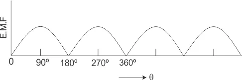
The commutator is a split ring attached to the loop. As the loop rotates, the commutator reverses the connection of the loop to the external circuit at every half-rotation. This ensures the output current flows in the same direction in the external circuit, resulting in direct current (DC). The brushes press against the commutator segments and collect the induced current. The output is a pulsating DC current because the EMF varies in magnitude but remains in the same direction.
At 90º rotation
In a single-loop DC generator, when the loop reaches a position where it is at 90° to the magnetic field (perpendicular to the field lines), significant changes occur in the generation of EMF.
At this position, the plane of the loop is parallel to the magnetic field lines, meaning the conductor is cutting the magnetic field lines at its maximum rate. This is when the rate of change of magnetic flux linkage is greatest.
According to Faraday’s Law, the magnitude of induced EMF is proportional to the rate at which the conductor cuts the magnetic lines of force.
At 90°, the conductor experiences the maximum rate of flux cutting, resulting in the maximum induced EMF.
As the loop rotates beyond the 90° position: The sides of the loop reverse their position relative to the magnetic field. Without a commutator, this would cause the direction of the current to reverse. The commutator ensures the output current remains in the same direction by reversing the connections of the loop to the external circuit.
This 90° position is a critical point in the generator’s operation, as it determines the peak of the pulsating DC output. since this is where the magnetic flux linkage is at fastest rate of change, Induced EMF is a maximum and Maintained as DC by the commutator
In a single-loop DC generator, when the loop reaches the 180° position (a half-rotation), the behaviour of the induced EMF and current direction undergoes specific changes
At 180° rotation:
The plane of the loop is again perpendicular to the magnetic field lines, similar to its initial position at 0°, but the loop has rotated by half a turn. At this point, the magnetic flux linkage through the loop is zero because the loop is parallel to the magnetic field, and the sides of the loop are no longer cutting through the field.
The rate of change of magnetic flux linkage is now zero at this precise instant. Consequently, the induced EMF at 180° is minimum (zero). However, as the loop continues past this point, the induced EMF starts to increase again, but its polarity (direction) would naturally reverse due to the change in orientation of the loop’s motion relative to the magnetic field.
Without a commutator, the polarity of the EMF would reverse, causing the current direction in the external circuit to reverse as well. The split-ring commutator corrects this by reversing the connection between the loop and the external circuit, ensuring that the output current remains in the same direction (direct current, DC).
At 180°, the induced EMF reaches a momentary zero before increasing again in the same direction, thanks to the action of the commutator. This ensures the output current remains pulsating DC rather than alternating
At 270º rotation
In a single-loop DC generator, the principle of electromagnetic induction is used to generate an electromotive force (EMF) as the loop rotates in a magnetic field.

At 270º, the plane of the loop is perpendicular to the direction of the magnetic field lines (the loop is vertical relative to the horizontal field lines).
The induced EMF is at its negative peak at this position because the rate of change of magnetic flux through the loop is at its maximum, and the flux linkage is decreasing most rapidly. Mathematically, the EMF can be represented as: e = Emax sin(θ)
At 270º: e = Emax sin(270º) = −Emax
The current reverses direction compared to 90º (when the EMF was at its positive peak).
The EMF waveform at this instant is moving toward completing a cycle in an AC waveform.
In a practical DC generator, this alternating EMF is converted into unidirectional current using a commutator. The commutator ensures that the output polarity remains constant, even as the loop rotates.
At 360º rotation
In a single-loop DC generator, at 360º (or 0º due to periodicity), the loop completes a full rotation. The loop is parallel to the magnetic field lines at 360º, just as it was at 0º. The magnetic flux through the loop is maximum because the plane of the loop is perpendicular to the magnetic field (aligned flat against the field lines). At this position, the rate of change of magnetic flux through the loop is zero because the loop is moving parallel to the field lines and not cutting them.
Therefore, the induced EMF is zero at this instant.
The EMF at 360º is described by: e = Emax sin(θ)
At θ = 360º e = Emaxsin(360º) = 0
The commutator in a DC generator converts the alternating EMF into unidirectional current. At 360º, even though the instantaneous EMF is zero, the output DC waveform will remain unidirectional and ripple-free due to the smoothing effect of the commutator.
Working Principle of DC Generator
In the first half of the revolution, the current constantly flows along the path ABLMCD, with brush No. 1 making contact with segment a.
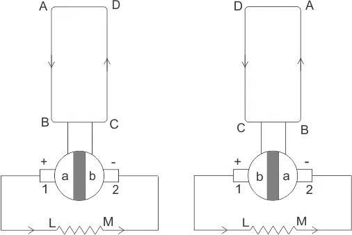
During the next half of the revolution, the direction of the induced current in the coil reverses. However, at the same time, the positions of segments a and b are also swapped. As a result, brush No. 1 now comes into contact with segment b.
This arrangement ensures that the current in the load resistance continues to flow in the same direction, from L to M. The waveform of the current through the load circuit, as shown in the diagram, is unidirectional.
This explanation illustrates the basic working principle of a DC generator using a single-loop generator model. The brushes in a DC generator are positioned so that the changeover between segments a and b occurs when the rotating coil is perpendicular to the magnetic field lines. At this point, the induced EMF in the coil is zero.
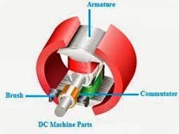
Construction of a DC generator
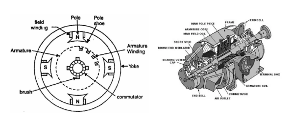
Yoke of DC Generator: is a crucial component of its construction, primarily serving structural and magnetic functions. The yoke is the outer frame or casing of the DC generator that supports and protects the internal components. It also serves as a part of the magnetic circuit.
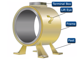
The yoke provides a low-reluctance path for the magnetic flux generated by the field poles. It completes the magnetic circuit between the poles of the generator. It serves as the mechanical backbone of the generator, housing the field poles and other internal components like the armature core and rotor. The yoke ensures structural rigidity and alignment of the internal parts. The yoke shields the internal parts of the generator from dust, moisture, and mechanical damage. It helps dissipate heat generated in the generator during operation, preventing overheating of the machine.
The material used for the yoke is selected based on its magnetic and mechanical properties:
Cast Iron: Commonly used in small generators due to its low cost and adequate mechanical strength. However, it has high magnetic reluctance and brittleness.
Cast Steel: Preferred in medium and large generators because of its superior magnetic and mechanical properties. It has lower reluctance, making it more efficient for magnetic flux conduction.
Rolled Steel: Used in modern generators due to its high mechanical strength, toughness, and better magnetic permeability.
The yoke is typically cylindrical or rectangular in shape, depending on the design of the generator. It must be thick enough to provide adequate magnetic flux conduction and mechanical stability while remaining lightweight for efficient machine operation.
Pole Cores and Pole Shoes of DC Generator
The pole cores and pole shoes are critical components of a DC generator, forming part of its magnetic system. They work together to ensure effective magnetic flux distribution and contribute to the generator’s overall performance
Pole Cores: are the central, vertical structures in the magnetic system of a DC generator. They are part of the poles and house the field windings (excitation coils). The pole cores hold the field windings in place, ensuring the magnetic field is produced effectively when current flows through the windings. The pole cores conduct the magnetic flux generated by the field windings to the air gap between the poles and the armature. Their cylindrical shape focuses the magnetic flux into the pole shoes for even distribution over the armature. Made of soft magnetic material (such as cast steel or laminated steel) to minimize hysteresis and eddy current losses.
Pole Shoes: are the extended, flat portions of the poles that spread the magnetic flux evenly over the surface of the armature. Pole shoes enlarge the cross-sectional area of the pole, ensuring the magnetic field is distributed uniformly across the armature. By covering a larger area, they reduce the magnetic reluctance of the air gap. They protect and secure the field windings in place, ensuring durability and operational stability. The extended design of the pole shoes reduces the air gap length, which decreases the magnetizing current and improves the machine’s efficiency. Made of soft magnetic materials, similar to the pole cores, and often laminated to reduce eddy current losses.
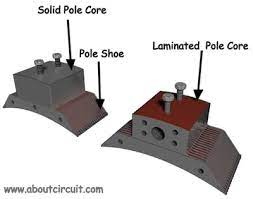
The pole cores and pole shoes are bolted or welded together, forming a single structural unit. Laminations are used in their construction to minimize core losses due to alternating magnetic fields. Together, the pole cores and pole shoes create a uniform and strong magnetic field in the air gap. This ensures smooth operation, minimizes vibrations, and enhances the performance of the DC generator
Armature Core of DC Generator plays a critical role in its operation. It is a cylindrical structure, typically made of laminated sheets of silicon steel, and is mounted on the shaft of the machine.
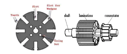
The armature core provides a sturdy structure to hold the armature winding (the conductive coils where the EMF is induced). The core provides a low-reluctance path for the magnetic flux produced by the field winding. This is essential for efficient energy conversion. To minimize energy losses due to eddy currents, the core is made of laminated sheets of silicon steel. These laminations are insulated from each other with a thin layer of varnish or oxide coating. By reducing the thickness of each lamination, the eddy current losses are significantly reduced. The silicon steel material used in the core reduces hysteresis losses, which occur due to the repeated magnetization and demagnetization of the core material during operation. The armature core is designed to dissipate the heat generated due to various losses (eddy current, hysteresis, and copper losses in the windings). Ventilation ducts are often included to allow better cooling.
Key Features of Armature Core; Laminated silicon steel for high magnetic permeability and low core losses. Laminations are stacked together and keyed to the shaft for mechanical stability. The outer surface of the core has slots to house the armature windings securely. The efficiency and output of a DC generator heavily depend on the armature core’s design. Proper lamination and material selection ensure low energy losses and long-term reliability.
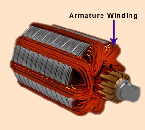
Armature Winding of DC Generator of a DC generator is the part where electromotive force (EMF) is induced due to the interaction between the magnetic field and the motion of the armature. It consists of insulated conductive wires placed in the slots of the armature core. The EMF Generator converts mechanical energy into electrical energy by inducing an EMF and carries the load current to the external circuit in the generator.
Lap Winding: In lap winding, the ends of each coil are connected to adjacent commutator segments, and the number of parallel paths equals the number of poles. Suitable for low voltage, high current applications. Number of parallel paths, A, equals the number of poles, P. Total conductors are divided among multiple parallel paths. Used in machines with high current output, such as welding generators.
Wave Winding: In wave winding, the coils are connected in such a way that the winding progresses around the armature in a wave-like pattern, connecting coils far apart. Suitable for high voltage, low current applications. Number of parallel paths, A, is always 2, irrespective of the number of poles. The same current flows through each winding. Used in machines with high voltage output, such as large DC generators.
Armature Windings are made of materials like copper to ensure high conductivity and minimal resistance. Proper insulation prevents short circuits between the windings or between the windings and the armature core. Must withstand the mechanical stresses caused by rotation and electromagnetic forces. Winding should allow heat dissipation to avoid overheating. There are two types of conductors in winding, these are Single-turn Coil: A single loop of conductor and Multi-turn Coil: Multiple turns of a conductor, increasing the induced EMF. The armature winding ends are connected to the commutator segments. The commutator works with the brushes to ensure the current output is unidirectional despite the alternating nature of the induced EMF in the armature winding. Common Issues include distortion of the main magnetic field due to armature current. Energy loss due to resistance in the winding. Improper commutation can lead to sparking.
Commutator of DC Generator
The commutator is a crucial component of a DC generator, responsible for converting the alternating current (AC) induced in the armature windings into unidirectional (DC) current at the output terminals. It works in conjunction with brushes to achieve this function.The commutator converts the alternating EMF generated in the armature into a direct current. Transfers current from the rotating armature to the stationary external circuit via brushes. Ensures that the direction of current in the external circuit remains constant
Construction of the Commutator: Segments are made of hard-drawn copper or an alloy. Shaped into bars or segments, insulated from each other with mica. Mica sheets are used to insulate the segments both from each other and from the shaft. The insulation prevents short circuits. Rigidly attached to rotate with the armature.
Working of the Commutator
As the armature rotates in the magnetic field, an alternating EMF is induced in the windings. The direction of the induced EMF reverses every half cycle as the coil moves under opposite magnetic poles. The commutator reverses the connections of the armature windings with the brushes at the same instant the EMF in the winding reverses. This ensures the current direction in the external circuit remains constant, producing a unidirectional DC output.
Brushes: Usually made of carbon or graphite for better conductivity and longer life. Brushes are placed on the commutator surface in a stationary position. Brushes collect the current from the rotating commutator segments and deliver it to the external load.
Key Features
Self-Rectifying: No external rectifier is needed, as the commutator performs this task mechanically.
Robust Design: Made to withstand mechanical stresses and high temperatures due to rotation and current flow.
Ease of Maintenance: Segments can be replaced individually when worn.
Challenges and Maintenance
Sparking: Improper commutation (timing issues) can lead to sparking at the brushes. Causes include worn-out brushes, dirty commutator surfaces, or armature reaction.
Wear and Tear: Continuous friction with brushes causes the commutator surface to wear down. Regular cleaning and resurfacing (turning) are necessary. Heating: High current flow and friction lead to heating, which requires effective cooling mechanisms.
Advantages of the Commutator include : Enables the generator to produce DC directly without the need for external rectifiers. Provides simplicity and reliability in small and medium-sized machines.
Limitations: Adds to the mechanical complexity of the machine. Subject to wear and requires regular maintenance. Not suitable for very high-speed or high-power applications, where electronic rectifiers are preferred.
Bearing of DC Generator
For small DC machines, ball bearings are typically used, while roller bearings are preferred for heavy-duty DC generators. Proper lubrication of the bearings is essential to ensure smooth operation and extend the generator’s lifespan.
Interested in our Electrical Engineering Courses?
At iLearn Engineering®, we offer a diverse range of online accredited electrical engineering courses and qualifications to cater to different academic and career goals. Our courses are available in varying credit values and levels, ranging from 40 credit Engineering Diplomas to a 360 credit International Graduate Diploma.
Short Courses (40 Credits)
A selection of our more popular 40 credit electrical diplomas…
Diploma in Electrical and Electronic Engineering
Diploma in Electrical Technology
Diploma in Renewable Energy (Electrical)
First Year of Undergraduate (Level 4 – 120 Credits)
Higher International Certificate in Electrical and Electronic Engineering
First Two Years of Undergraduate (Level 5 – 240 Credits)
Higher International Diploma in Electrical and Electronic Engineering.
Degree equivalent Graduate Diploma (Level 6 – 360 Credits)
International Graduate Diploma in Electrical and Electronic Engineering
All Electrical and Electronic Courses
You can read more about our selection of accredited online Electrical and Electronic Engineering courses here.
Complete Engineering Course Catalogue (all courses)
Alternatively, you can view all our online engineering courses here.
Recent Posts
Civil Engineering Courses and Diplomas: Topics, Skills and Career Routes
Civil Engineering Courses and Diplomas: Topics, Skills and Career Routes Introduction Civil engineering is the backbone of modern society. From roads and bridges to skyscrapers and water systems, civil engineers design, build, and maintain the infrastructure that keeps the world running. If you’re considering a civil engineering course or diploma, understanding what it covers is […]
What Is a Diploma in Engineering? Courses, Levels and Career Routes Explained
What Is a Diploma in Engineering? Courses, Levels and Career Routes Explained Introduction Engineering shapes the world around us, from the buildings we live in to the technology we use every day. But for many aspiring engineers, the biggest question is not whether to pursue engineering, but how to start. Traditional university degrees are not […]
Engineering Courses: How to Choose the Right Route for Your Career
Engineering Courses: How to Choose the Right Route for Your Career Introduction Choosing an engineering course can feel like standing at the beginning of several different roads, each leading towards a different kind of future. One route may lead into mechanical systems and manufacturing. Another may lead towards aircraft, infrastructure, electronics, computing, renewable energy or […]