Understanding the Characteristics of Different Electric Motors
Introduction
The choice of motor type is crucial to ensure that a system meets its performance, efficiency, and cost requirements. Selecting the appropriate motor depends on factors such as required speed, torque, power output, control precision, and operating environment. By analysing these criteria, engineers can justify the selection of a particular motor, such as a DC, induction, or stepper motor, based on how well its characteristics align with the specific application’s demands.
DC Motor Characteristics
When selecting a DC motor for an application, several key criteria must be considered to ensure that the motor meets the performance, efficiency, and cost requirements.
Below are the most critical factors:
- Power Requirements including voltage, current and power
- Load characteristics including torque, inertia and speed.
- Duty cycle including continuous or intermittent operation, load variation and thermal management.
- Efficiency
- Control requirements including speed control, position control and ease of integration.
- Motor type including brushed and brushless
- Environment including temperature range, humidity and exposure to moisture.
- Enclosure type: Open or sealed
- Noise and vibration
- Size and weight constraints:
- Cost balance initial cost with performance and operating costs.

DC Shunt Motor Characteristics
Torque – Current Characteristics (T v/s Ia)
We know that, T α Iaφ
But the flux of a shunt motor is practically constant. Therefore,
T α Ia
If we plot these of a graph we will get a straight line, passing through the origin.
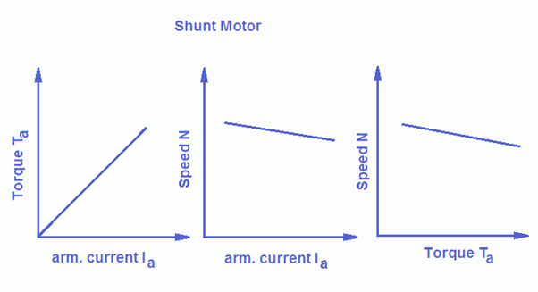
Although the field current remains practically constant,d ue to armature reaction, the field flux becomes slightly weaker at heavy loads. This can sometimes be seen by a slight curve at the end.
Speed- Current Characteristic (N v/s Ia)
Back EMF of shunt motor is given by Eb = V – IaRa = (PφNZ)/60A
Because P, N, Z and A are constant Eb α Nφ or V – IaRa α Nφ or N α (V – IaRa)/φ …….(1)
The field flux of a shunt motor is almost constant. Therefore, the numerator of RHS of equation (1) decreases with increase in load (or Ia). So there is a little fall in speed with the increase in load, hence the curve bends slightly as the load is increased due to increased IaRa voltage drop.
Speed – Torque Characteristics (N v/s T) : The speed torque characteristics are similar to speed current characteristics.
DC Series Motor Characteristics
Torque – Current characteristics (T v/s Ia)
Torque α Armature current x Field flux T α Iaφ
Before saturation, φ α Ia
After magnetic saturation of the core, flux (φ) is independent of Ia i.e. flux does not increase with increase in armature current.
Therefore after saturation, T α Ia
Therefore, on light loads, the torque produced by the series motor is proportional to the square of armature current and hence the curve drawn between torque and armature current up to magnetic saturation is a parabola. But after magnetic saturation flux φ is independent of excitation current and so torque is proportional to Ia and hence characteristics become a straight line.
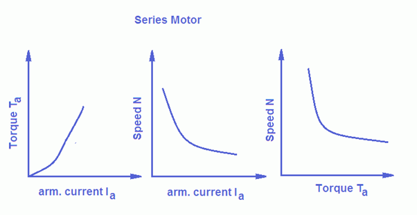
Speed – Current Characteristics (N v/s Ia)
We know that Eb = (PφNZ)/60A or N = (60AEb)/PφZ
In the above equation, all quantities are constant except Eb and φ.
N α Eb / φ also Eb = V – Ia Ra
combining the equations N α (V – IaRa) / φ
Initially the field flux φ rises in proportion to the current but after saturation, it is independent of armature current. Consequently, speed N is roughly proportional to the current. The speed may become dangerously high if load reduces to a small value. A DC series motor should not run on no-load and are always connected to loads by gears so that minimum load is always maintained to keep the speed within safe limits.
Speed – Torque Characteristics (N v/s T)
A series motor develops high starting torques at low speeds and low torque at high speeds, This is represented by a hyperbola. High starting torque enables even a small series motor to start a heavy load.
DC Compound Motor Characteristics
A DC compound motor combines the features of series and shunt motors, offering a balance between high starting torque and good speed regulation. It is achieved by having two windings on the stator: one connected in series with the armature and the other in parallel (shunt) with it.
Types of Compound Motors:
Cumulative Compound Motor where series and shunt field windings aid each other, producing a stronger overall magnetic field. Offers high starting torque and better speed regulation than a series motor.
Differential Compound Motor where series and shunt windings oppose each other, leading to weaker field strength. Not commonly used due to poor performance and instability under load variations.
Torque Characteristics: High starting torque due to the series winding component. Better torque control compared to a pure series motor.
Speed Characteristics: Speed varies less with load changes compared to a series motor. Cumulative compound motors maintain a relatively constant speed under varying loads.
Load Handling: Suitable for applications with sudden load changes. Can handle heavy starting loads effectively.
Current Characteristics: Draws high current during startup. Stable operation under normal conditions, thanks to the shunt winding.
Reversibility: The motor’s direction can be reversed by changing the polarity of the armature or field windings.
Advantages: Versatility: Combines the benefits of series and shunt motors. High Starting Torque: Suitable for heavy loads. Good Speed Regulation: Provides stable operation across varying loads. Flexible Design: Can be designed to favour torque, speed regulation, or both.
Disadvantages Complexity: More components than series or shunt motors. Cost: Higher cost due to the additional windings. Efficiency: Slightly lower efficiency than simpler motor designs.
Comparison with Other DC Motors
Compound motor characteristics basically depend on the fact whether the motor is cumulatively compound or differential compound. All the characteristics of the compound motor are the combination of the shunt and series characteristics.
Torque – Current Characteristics
In the case of a cumulative compound motor, as the armature current increases, the series flux increases, so flux per pole increases.
But T α Iaφ
Consequently torque also increases; however, this increase in torque is greater than that of the shunt motor.
In a differential compound motor, the series field opposes the shunt field so the total flux of such a motor decreases with increase in current (i.e. load). This means that in a differential compound motor, torque increases with increase in current.
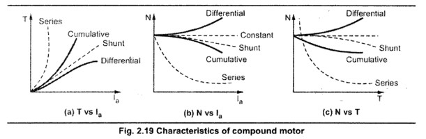
In a differential compound motor, as two fluxes oppose each other, the resultant flux will decrease as load increases, as a result of this the machine runs at a higher speed with an increase in load. This property is dangerous as on full load, the motor may try to run at dangerously high speed. So the differential compound motor is generally not used in practice.
The exact shape of these characteristics depends on the relative contribution of series and shunt field windings. If the shunt field winding is more dominant then the characteristics take the shape of the shunt motor characteristics. While if the series field winding is more dominant then the characteristics take the shape of the series characteristics.
Characteristics of a Stepper Motor
In stepper motors, the electromagnetic torque varies with the stepping rate (in pulses per second, PPS), and this relationship is key to understanding motor performance. Here’s an overview of this phenomenon:
Torque-Speed Characteristics
Low Stepping Rate (Low PPS): At lower stepping rates, the rotor has sufficient time to align fully with the magnetic field of each stator pole. The torque produced is relatively high because the motor operates near its holding torque, which is the maximum torque it can exert when stationary.
Moderate Stepping Rate: As the stepping rate increases, the rotor has less time to align with the changing stator fields. The torque starts to decrease because the rotor can’t keep up with the rapidly changing magnetic field.
High Stepping Rate (High PPS): At very high stepping rates, the torque drops significantly because the rotor lags behind or fails to synchronise with the stator field changes. This condition can lead to a loss of steps or stalling if the load torque exceeds the available torque.
Key Points in the Torque-PPS Curve
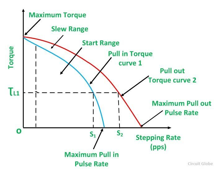
Pull-In Torque: Represents the maximum torque the motor can exert to start moving from rest at a given stepping rate without losing synchronisation.
Pull-Out Torque: Indicates the maximum torque the motor can sustain at a given stepping rate while already in motion without stalling.
Resonance Zones: Stepper motors can exhibit resonant behaviour at certain stepping rates, leading to vibrations or torque dips. Dampening techniques or microstepping can mitigate this effect.
The torque-PPS curve typically starts with a high torque at low PPS, decreases gradually as the PPS increases, and drops steeply beyond a certain threshold, where the motor can no longer maintain synchronisation. This relationship is important for designing stepper motor applications to ensure the motor operates within its optimal torque-speed range, avoiding excessive loads or overspeeding that could lead to instability or inefficiency.
Characteristics of Induction Motors
Induction motors, widely used in industrial and domestic applications, exhibit specific characteristics that define their performance. These characteristics can be grouped into electrical, mechanical, and operational aspects. Here’s a detailed overview:
Torque-Speed Characteristics
Starting Torque: The torque produced at zero speed (when the motor starts). Higher in slip-ring (wound-rotor) induction motors compared to squirrel cage motors.
Pull-Out Torque (Maximum Torque): The maximum torque the motor can produce without stalling. Typically 2-3 times the rated torque.
Running Torque: The torque developed during normal operation, usually equal to the load torque.
Breakdown Torque: The maximum torque the motor can handle before the speed drops significantly.
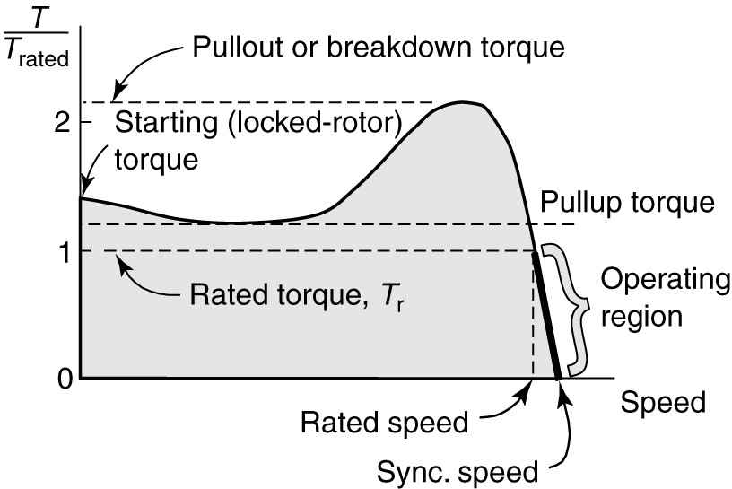
Torque-Speed Curve The curve is non-linear, starting with a steep rise (high starting torque), reaching a peak (maximum torque), and then dropping as speed approaches synchronous speed.
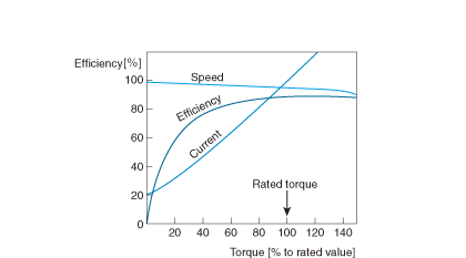
Efficiency: Induction motors have good efficiency, typically between 85% to 97% at full load. Efficiency drops at partial loads or under lightly loaded conditions.
Power Factor: Induction motors generally have a lagging power factor due to their inductive nature. The power factor is low at no load and improves as the load increases.
Speed Regulation: Induction motors exhibit poor speed regulation, meaning their speed decreases slightly as the load increases. The speed is determined by the supply frequency and the number of poles, with slip accounting for the speed difference between synchronous and actual speed.
Slip: Slip is the percentage difference between synchronous speed and rotor speed:
Slip = (Synchronous Speed – Rotor Speed) x 100
Synchronous Speed
Typical slip values range from 0.5% to 6% under full load.
Starting Methods: Direct-On-Line: Simple and commonly used for small motors.Star-Delta Starter: Reduces starting current. Autotransformer Starter: Provides a reduced voltage at startup. Soft Starters: Gradually increase voltage. Variable Frequency Drives: Offer precise control of starting, speed, and torque.
Speed control methods include:Changing Supply Frequency (using VFDs)., Changing Stator Voltage (less common, for small speed adjustments). Rotor Resistance Control (for wound-rotor motors).
Types of Induction Motors Squirrel Cage Motors which are simple, robust, and require less maintenance. Used in constant-speed applications. Slip-Ring (Wound-Rotor) Motor which provides high starting torque and better speed control. Used in heavy-duty and variable-speed applications.
Advantages: Simple construction and robust design. Low cost and maintenance requirements.Reliable and durable.
Disadvantages: Lower starting torque in squirrel cage motors. Poor speed control without additional equipment. Operates with lagging power factor.
Characteristics of Synchronous Motor
A synchronous motor is a type of AC motor where the rotor speed matches the synchronous speed of the stator’s rotating magnetic field. This motor type exhibits unique characteristics that make it suitable for various industrial applications.
Speed Characteristics
A synchronous motor runs at a constant speed (synchronous speed) irrespective of the load, given by:
Synchronous Speed (Ns) = 120f / P
where f is the supply frequency in Hz and P is the number of poles.
The speed does not change with load variations, making it ideal for precision applications.
Torque Characteristics
Starting Torque: Synchronous motors typically have no starting torque and cannot self-start. They require auxiliary means (e.g., pony motors or damper windings) to reach near-synchronous speed.
Pull-In Torque:The maximum torque the motor can develop to pull into synchronous speed after being started.
Pull-Out Torque:The maximum torque the motor can sustain without losing synchronism. This value is typically 1.5 to 3 times the rated torque.
Power Factor: Synchronous motors have an adjustable power factor and can operate at leading, lagging, or unity power factor by adjusting the excitation of the rotor field. Over-excitation leads to a leading power factor (used for power factor correction). Under-excitation results in a lagging power factor.
Efficiency: Synchronous motors are highly efficient, especially under full-load conditions, due to reduced losses compared to induction motors.
Starting Requirements: Synchronous motors require an auxiliary device to start since they cannot develop starting torque on their own.Common starting methods include: Using an external motor (pony motor). Damper windings provide starting torque like an induction motor. Variable frequency drives for smooth starting.
Load Characteristics: The speed remains constant regardless of load changes until the pull-out torque is exceeded.
Load-Dependent Excitation: As load increases, the excitation must be adjusted to maintain synchronism and optimise the power factor.
Stability: A synchronous motor is stable within its pull-out torque limit. Exceeding this limit results in loss of synchronism and motor stalling.
Construction and Types: Rotor Construction can be cylindrical (non-salient) poles for high-speed applications (e.g., turbo-generators), or salient poles for low-speed applications requiring high torque.
Advantages: Ideal for applications where precise speed regulation is required. Operates at a leading power factor, improving the overall power factor of the system. High efficiency due to reduced slip losses. Suitable for both low-speed and high-speed applications.
Disadvantages: Non-Self Starting: Requires additional equipment or methods to achieve synchronous speed. Complexity: Requires excitation systems and additional starting mechanisms. More expensive than induction motors of similar ratings. Motor operation becomes unstable if the load exceeds the pull-out torque.
Interested in our Electrical Engineering Courses?
At iLearn Engineering®, we offer a diverse range of online accredited electrical engineering courses and qualifications to cater to different academic and career goals. Our courses are available in varying credit values and levels, ranging from 40 credit Engineering Diplomas to a 360 credit International Graduate Diploma.
Short Courses (40 Credits)
A selection of our more popular 40 credit electrical diplomas…
Diploma in Electrical and Electronic Engineering
Diploma in Electrical Technology
Diploma in Renewable Energy (Electrical)
First Year of Undergraduate (Level 4 – 120 Credits)
Higher International Certificate in Electrical and Electronic Engineering
First Two Years of Undergraduate (Level 5 – 240 Credits)
Higher International Diploma in Electrical and Electronic Engineering.
Degree equivalent Graduate Diploma (Level 6 – 360 Credits)
International Graduate Diploma in Electrical and Electronic Engineering
All Electrical and Electronic Courses
You can read more about our selection of accredited online Electrical and Electronic Engineering courses here.
Complete Engineering Course Catalogue (all courses)
Alternatively, you can view all our online engineering courses here.
Recent Posts
Visual Management Systems: See It, Own It, Improve It
Visual Management Systems: See It, Own It, Improve It Introduction All manufacturing companies use Key Performance Indicators (KPIs) in order to provide a fast and visual response to these questions. One of the most simple, but important tools, is a Visual system known as a SQCDP Board. A SQCDP Board is a visual management board […]
5S and Lean Manufacturing: Building Efficiency from the Ground Up
5S and Lean Manufacturing: Building Efficiency from the Ground Up Introduction Lean manufacturing is built on the principle of eliminating waste while maximizing productivity, quality, and efficiency. However, before any lean strategy can deliver lasting results, organizations need a strong operational foundation, and that foundation begins with 5S. The 5S methodology is more than just […]
Kaizen and Continuous Improvement: Benefits, Challenges, and Impact
Kaizen and Continuous Improvement: Benefits, Challenges, and Impact Introduction Continuous improvement is a management philosophy focused on making ongoing, incremental improvements to processes, products, and workplace culture. One of the most recognised approaches to continuous improvement is Kaizen, a Japanese philosophy meaning “change for the better.” Developed and popularised in Japanese manufacturing industries, particularly Toyota, […]