Essential Formulas for Calculating Drilling Parameters
When it comes to precision and efficiency in manufacturing, few processes are as foundational—or as critical—as drilling. Whether you’re a seasoned engineer or a student entering the world of mechanical or industrial engineering, understanding how to correctly calculate drilling parameters can significantly impact the quality of your work, the lifespan of your equipment, and the overall productivity of your operations.
This guide demystifies the essential formulas used in drilling calculations, providing you with practical tools to determine cutting speeds, spindle speeds, feed rates, and material removal rates. Armed with these formulas, you’ll be able to make more informed decisions on the shop floor or in academic assessments, ensuring optimal performance across a range of applications.
The below collection of equations can be used to calculate specific parameters during turning, drilling, and milling. Knowing the correct speeds, feeds, and depths of cut are critical for successful drilling.
Knowing cutting forces is important to ensure you select the correct type of tool for the job, such as the material of the tool (HSS vs solid carbide for example), and the safe amount of material you can remove at each pass without risk to the workpiece or the cutter.
All calculations below are assuming metric sizing; however the format of the equations can be also used for imperial sizes with the correct translation from metric to imperial.
Cutting speed (VC), m/min
Vc = Dc x π x n / 1000
Where DC = Diameter of the cutter in mm, and n = spindle speed in RPM
Spindle Speed (n), RPM (revs per minute)
n = Vc x 1000 / π x Dc
Where DC = Diameter of the cutter in mm, VC = cutter speed
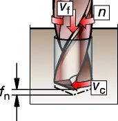
Penetration Rate (Vf) mm/min
This formula is used to link the below two parameters:
Penetration rate (Vf) – (longitudinal speed at which the drill is cutting into the material)
Feed per Revolution’ (fn) – the depth of material cut for each full revolution of the drill.
Vf = fn x n
where n = spindle speed, fn = Feed per revolution (mm/rev)
Material Removal Rate (Q), cm3/min
Q = Dc x fn x Vc / 4
Machining Time (TC), min
Tc = Lm / Vf
Where Lm = length of material to be drilling (m)
Net Power (Pc) kW
Pc = fn x Vc x Dc x Kc / 240×103
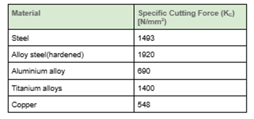
where KC = Specific Cutting force. (This is defined as the force needed to cut a chip area of 1 mm² that has a thickness of 1 mm).
Example KC values are given below:
Torque (MC), Nm
Mc = Pc x 30 x103 / π x n
Example Drilling Calculation
Calculate:
i) The appropriate spindle speed
ii) material removal rate
iii) total machining time to drill 120 holes (assume 10 seconds set-up per hole)
iv) net power consumption
v) drilling torque required…
…for a 12mm HSS drill, drilling through 80 mm thick aluminium alloy. Take the appropriate cutting speed for the material to be 60m/min, feed per revolution to be 0.1mm/rev and specific cutting force required to be 690N/mm2.
i) Spindle speed, n:
n = Vc x 1000 / π x Dc
n = 60 x 1000 / π x 12
n = 1592 RPM
ii) material removal rate, Q:
Q = Dc x fn x Vc / 4
Q = 12 x 0.1 x 60 / 4
Q = 18.0cm3/min
iii) Total machining time, TC
Tc = Lm / Vf
Vf = fn x n = 0.1 x 1592 = 159.2 mm/ min
Tc = 80 / 159.2 = 0.5 min per hole
Therefore for 120hole = 0.5 x 120 = 60mins
+ setup time of 10 seconds per hole = 120 x 10 = 1200 seconds = 20 mins
Total time = 60+20 = 80minutes
iv) net power consumption
Pc = fn x Vc x Dc x Kc / 240×103
Pc = 0.1 x 60 x 12 x 690 / 240 x 103
Pc = 0.207kW
v) torque required
Mc = Pc x 30 x103 / π x n
Mc = 0.207 x 30×103 / π x 1592
Mc = 1.24Nm
Interested in our engineering courses?
We have over 70 courses across all major engineering disciplines, including, mechanical, electrical and electronic, civil, aerospace, industrial, computer and general engineering. Visit our course catalogue for a complete list of fully accredited engineering programmes.
A small selection of short courses …
Level 6 Courses
International Graduate Diploma in Mechanical Engineering
Level 5 Courses
Higher International Diploma in Industrial Engineering
Higher International Diploma in Mechanical Engineering
Level 4 Courses
Higher International Certificate in Industrial Engineering
Higher International Certificate in Mechanical Engineering
Alternatively, you can view all our online engineering courses here.
Recent Posts
Civil Engineering Courses and Diplomas: Topics, Skills and Career Routes
Civil Engineering Courses and Diplomas: Topics, Skills and Career Routes Introduction Civil engineering is the backbone of modern society. From roads and bridges to skyscrapers and water systems, civil engineers design, build, and maintain the infrastructure that keeps the world running. If you’re considering a civil engineering course or diploma, understanding what it covers is […]
What Is a Diploma in Engineering? Courses, Levels and Career Routes Explained
What Is a Diploma in Engineering? Courses, Levels and Career Routes Explained Introduction Engineering shapes the world around us, from the buildings we live in to the technology we use every day. But for many aspiring engineers, the biggest question is not whether to pursue engineering, but how to start. Traditional university degrees are not […]
Engineering Courses: How to Choose the Right Route for Your Career
Engineering Courses: How to Choose the Right Route for Your Career Introduction Choosing an engineering course can feel like standing at the beginning of several different roads, each leading towards a different kind of future. One route may lead into mechanical systems and manufacturing. Another may lead towards aircraft, infrastructure, electronics, computing, renewable energy or […]