What are Gyroscopes and how to analyse their torque?
This blog will look at how when torque is applied to a device known as a gyroscope, the output torque can be identified and calculated, the applications of this device will be discussed and the underlying principles behind the operation of a gyroscope will be analysed.
A gyroscope is a mechanical device that essentially consists of a spinning mass that rotates around its axis. This mass is supported by two gimbals as depicted in the diagram below.
The gyroscope’s frame in turn supports the gimbals. The gimbals are pivoted supports that allow the rotation of an object around an axis.
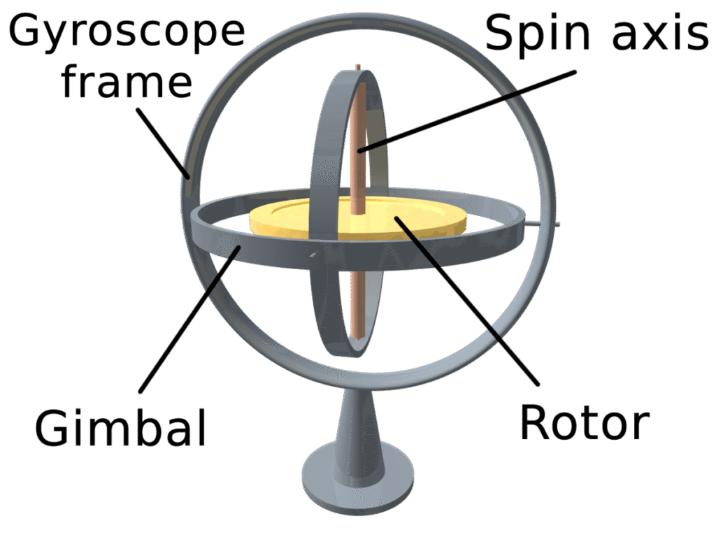
Notice the freedom of rotation of the spinning mass in the axis with the gimbals.
The spinning mass is connected to the frame, which can act as a gimbal, through an axle; it is this axle which defines the spin axis for the mass.
The spinning mass, or rotor, is constrained to spin about this axis, which is always perpendicular to the innermost gimbal.
The operation of the gyroscope relies upon is that when the rotor is spinning, the rotating mass will tend to keep its angular position with respect to an inertial reference frame, in this case the gimbal. This effect is so strong that it can support the gyroscope and seemingly defy gravity.
This phenomenon can be explained, firstly, by considering the angular momentum that the rotor will have and the fact that this angular momentum will have to be conserved.
Momentum is a combination of mass and velocity, and as velocity is a vector, this is dependent on the direction. Therefore, an object with angular momentum will resist a change in orientation as this is effectively the same as a change in angular momentum.
We will now consider what is known as gyroscopic precession.
The diagram below shows two examples of a spinning mass, when the mass is still and when the mass is spinning.
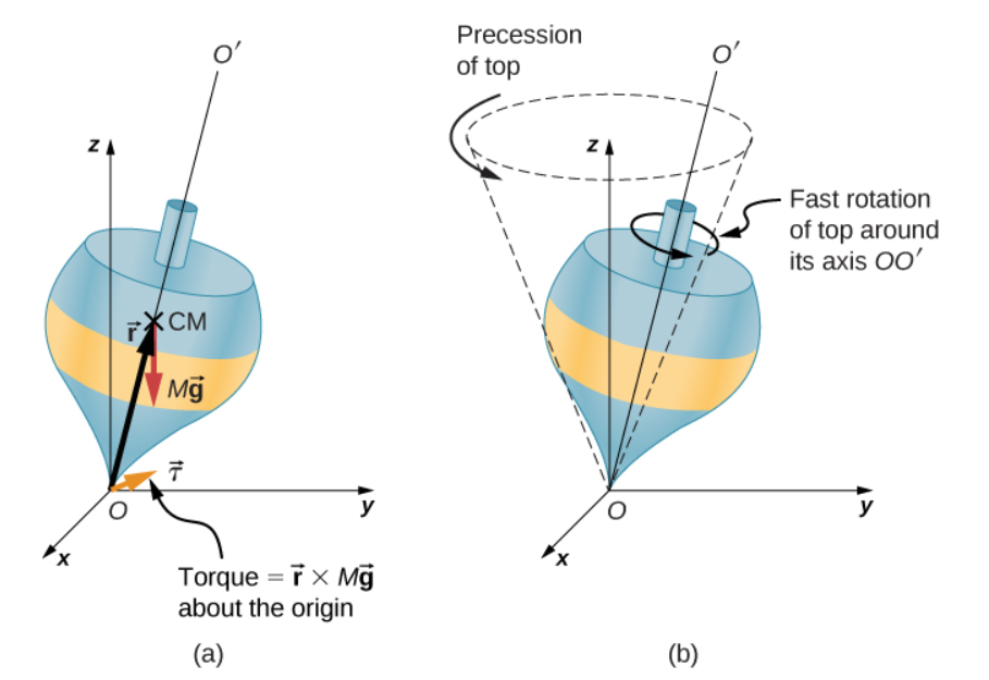
When the mass is stationary and placed upright at an angle to the vertical, it will simply fall over, due to the force of gravity (mg) producing a torque acting on its centre of mass (CM).
If the top is spinning, it does not topple over due to this torque from gravity, but rather precesses about the vertical.
Precession can be thought of as a repeated motion indicated by the dotted lines in the above figure. It processes in this way due to the torque on the centre of mass, which is changing the angular momentum.
If we consider the forces acting on the spinning gyroscope in more detail we can see that the torque (τ) produced is perpendicular to the angular momentum vector (L). As shown below.
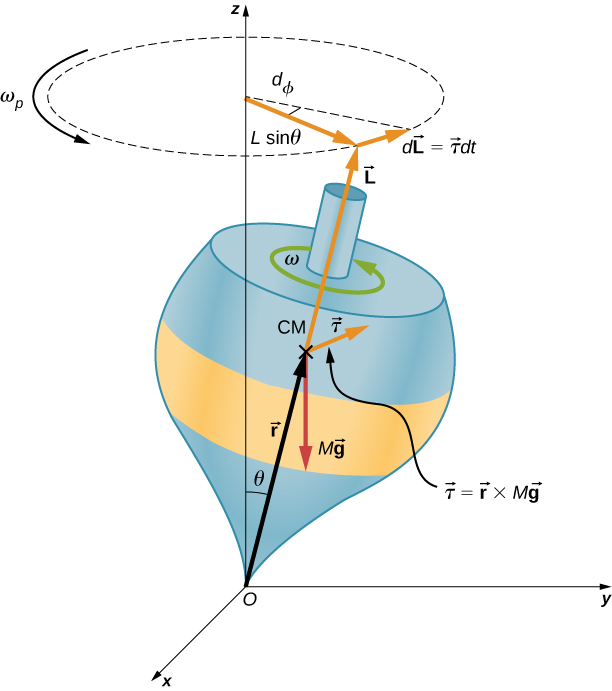
The torque is responsible for changing the direction, not magnitude, of angular momentum according to the expression
dL = τ dt.
Over time, in practice friction would cause a decrease in angular momentum, as the torque becomes less the precession would become larger and the spinning top would eventually topple over.
The larger this angular momentum is, the more difficult it is to change the direction of the spinning mass. The larger the change in momentum that is applied to the spinning mass also creates a larger resistance to the change in momentum.
This has practical applications for gyroscopes and they are commonly used in navigation and guidance systems as they detect changes in angular momentum and hence can maintain orientation.
We will now focus on mathematically calculating the torque produced from gyroscopic motion and apply this to some practical examples. Firstly, we consider the moment of inertia (I) a mass would possess before we apply angular momentum to it.
The moment of inertia is a property that determines the torque required for a specific angular acceleration around a rotational axis. The higher the moment of inertia is for an object the more torque we would need to apply to make it accelerate. The moment of inertia for an object depends on the mass of the object and the distribution of the object’s mass from its centre of rotation.
In the case of a gyroscope and the examples given in this blog we will be analysing the moment of inertia for a solid disc (the shape of spinning mass in a gyroscope)
The moment of inertia for a solid disc .
I = mr2 / 2
Where r is the radius of the disc (m)
M is the mass of the disc (kg)
I is the moment of inertia ( kgm2)
The torque required to accelerate a solid disc, or any shape, around a rotational axis with a moment of inertia, I, is given by.
T = I α
Where T is torque (Nm)
I is moment of inertia (kgm2)
α is the angular acceleration ( rads-2)
Example:
A solid disc is accelerating with an angular acceleration of 3 rads-2. The solid disc has a diameter of 0.4 m and a mass of 25 kg. Calculate the magnitude of torque required to produce this angular acceleration.
Firstly we must find the moment of inertia of the disc.
I = mr2/2 = 25 x 0.22 / 2 = 0.5 kgm2
The toque can now be found
T = I α = 0.5 x 3 = 1.5 Nm
Interested in our engineering courses?
We have over 70 courses across all major engineering disciplines, including, mechanical, electrical and electronic, civil, aerospace, industrial, computer and general engineering. Visit our course catalogue for a complete list of fully accredited engineering programmes.
A small selection of short courses …
Diploma in Mechanical Engineering
Diploma in Structural Engineering
Level 6 Courses
International Graduate Diploma in Mechanical Engineering
International Graduate Diploma in Civil Engineering
International Graduate Diploma in Aerospace Engineering
Level 5 Courses
Higher International Diploma in Mechanical Engineering
Higher International Diploma in Civil Engineering
Higher International Diploma in Aerospace Engineering
Level 4 Courses
Higher International Certificate in Mechanical Engineering
Higher International Certificate in Civil Engineering
Higher International Certificate in Aerospace Engineering
Alternatively, you can view all our online engineering courses here.
<
Recent Posts
Civil Engineering Courses and Diplomas: Topics, Skills and Career Routes
Civil Engineering Courses and Diplomas: Topics, Skills and Career Routes Introduction Civil engineering is the backbone of modern society. From roads and bridges to skyscrapers and water systems, civil engineers design, build, and maintain the infrastructure that keeps the world running. If you’re considering a civil engineering course or diploma, understanding what it covers is […]
What Is a Diploma in Engineering? Courses, Levels and Career Routes Explained
What Is a Diploma in Engineering? Courses, Levels and Career Routes Explained Introduction Engineering shapes the world around us, from the buildings we live in to the technology we use every day. But for many aspiring engineers, the biggest question is not whether to pursue engineering, but how to start. Traditional university degrees are not […]
Engineering Courses: How to Choose the Right Route for Your Career
Engineering Courses: How to Choose the Right Route for Your Career Introduction Choosing an engineering course can feel like standing at the beginning of several different roads, each leading towards a different kind of future. One route may lead into mechanical systems and manufacturing. Another may lead towards aircraft, infrastructure, electronics, computing, renewable energy or […]