

Why There Is No Perfect Aerofoil: The Design Trade-Offs Behind Every Aircraft Wing
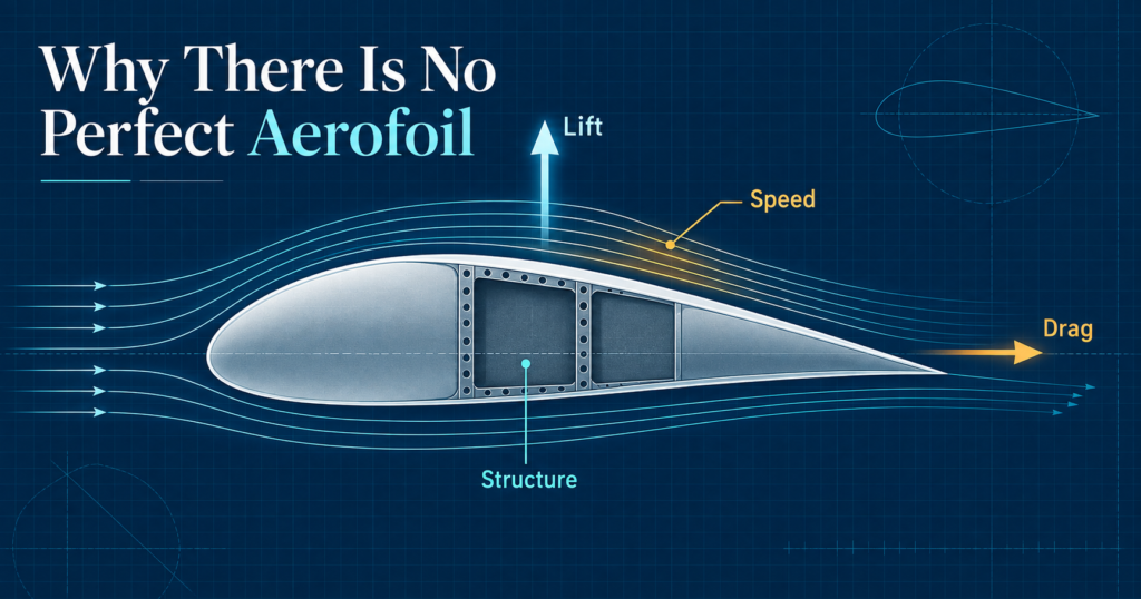
If a designer could create a perfect aerofoil, it would produce very high lift with almost no drag, remain stable at every angle of attack, fit a lightweight structure inside the wing and work equally well at low and high speed.
No real aerofoil can do all of those things at once.
Every aircraft wing is the result of compromise. A shape that improves low-speed lift may increase drag at cruise. A thin section that performs well at high speed may leave less room for spars, fuel and control systems. A long, slender wing can reduce induced drag, but it also increases structural bending loads.
The central question is therefore not, “What is the best aerofoil?” It is, “What aerofoil and wing design best meets this aircraft’s purpose?”
What does an aircraft wing need to achieve?
A wing must generate enough lift for the aircraft’s required flight conditions, while limiting drag, weight and undesirable pitching behaviour. It must also accommodate structure and, in many aircraft, fuel, landing gear attachments or high-lift devices.
Designers typically consider the following priorities:
- A sufficiently high maximum lift coefficient for take-off, climbing and landing.
- A good lift-to-drag ratio for efficient flight.
- Low drag at the intended cruise speed.
- Predictable aerodynamic moments and stable control behaviour.
- Enough depth for a structurally efficient wing box and spars.
- Acceptable performance across the aircraft’s full flight envelope.
These priorities frequently conflict. Improving one may weaken another.
Lift versus drag: more is not always better
A wing needs lift to support the aircraft’s weight, but lift is not free. Generating lift changes the pressure distribution around the wing and, for a finite wing, creates induced drag.
The total drag coefficient can be represented simply as:
Cd = Cd₀ + Cdi
Where Cd₀ is the zero-lift drag coefficient and Cdi is the induced drag coefficient.
Induced drag rises strongly as lift coefficient increases. NASA expresses the relationship as:
Cdi = CL² / (π × AR × e)
Where CL is lift coefficient, AR is aspect ratio and e is the span-efficiency factor. [1]
This explains why a wing designed to create very high lift at low speed may not be the most efficient shape for high-speed cruise. It also explains why a designer does not simply increase wing area or camber indefinitely.
A practical aircraft must generate sufficient lift where it matters most, while avoiding excessive drag during the larger proportion of its flight.
Camber: useful lift, but with a cost
Camber is the curvature of an aerofoil’s mean line. A cambered aerofoil can generate positive lift at a lower angle of attack than a symmetrical aerofoil, making it useful for conventional aircraft that need efficient low-speed performance.
Increasing camber can improve the available lift coefficient. However, it can also increase profile drag and create a larger pitching moment. The aircraft’s tailplane must then provide a balancing force, which can itself add drag.
This makes camber a design choice rather than a universal improvement.
A training aircraft, for example, may benefit from an aerofoil that produces predictable low-speed lift and benign stall characteristics. A high-speed aircraft may accept lower low-speed efficiency in return for reduced drag and more suitable behaviour at higher Mach numbers.
The relationship between pressure distribution, aerodynamic force and pitching moment is important here. As angle of attack changes, the pressure distribution changes; this can move the centre of pressure and alter the moment acting on the aerofoil. [2]
Thickness: aerodynamics must make room for structure
Aerofoil thickness is not just an aerodynamic feature. It is also a structural decision.
A thicker wing can provide more room for spars, ribs, fuel tanks, landing-gear mechanisms and control systems. Greater structural depth can allow a spar to carry bending loads more efficiently, potentially reducing structural mass for a required level of strength.
However, thickness must be managed carefully. A thicker aerofoil can increase drag, and at higher subsonic speeds it may encourage local airflow to accelerate towards sonic conditions sooner. This can become important for fast aircraft approaching the transonic regime.
The compromise can be seen clearly in aircraft wing design:
- Gliders often use wings that prioritise aerodynamic efficiency and low induced drag.
- Transport aircraft need efficient cruise performance, internal fuel volume, robust structure and useful low-speed handling.
- Fast jets may use thinner wings to manage high-speed aerodynamic effects, even though this makes structural layout more challenging.
For a more detailed explanation of the internal members that allow a wing to carry aerodynamic loads, read Why Aircraft Wing Structure Matters More Than You Think.
Aspect ratio: why long wings are not always the answer
Aspect ratio compares a wing’s span with its area.
AR = b² / S
For a rectangular wing, it can also be expressed as:
AR = b / c
Where b is wingspan, S is wing area and c is chord length.
A high-aspect-ratio wing is long and slender. It generally produces less induced drag for a given lift than a low-aspect-ratio wing. This is why gliders use long wings: reducing induced drag improves their lift-to-drag ratio and allows them to travel further for a given loss of height.
But longer wings create greater bending moments at the wing root. They can therefore require a heavier or more sophisticated structure. They may also be less practical where compactness, manoeuvrability, high-speed performance or ground clearance are priorities.
The right aspect ratio depends on the mission:
- A sailplane benefits strongly from a high aspect ratio.
- An airliner balances efficiency with structural mass, airport-gate limits and fuel capacity.
- A fighter aircraft may use a lower aspect ratio to suit high-speed flight and manoeuvrability.
This is why wing planform cannot be selected by aerodynamic efficiency alone. It must be considered alongside structure, operational use and the intended flight envelope.
Stability and the movement of aerodynamic forces
Aircraft designers also need the wing to behave predictably as flight conditions change.
The centre of pressure is the effective location at which the overall aerodynamic force acts. As angle of attack changes, the pressure distribution around an aerofoil changes too. If the resulting force moved significantly, it could create large changes in pitching moment and make the aircraft more difficult to trim and control.
For analysis, engineers often use the aerodynamic centre rather than relying solely on the moving centre of pressure. For many low-speed aerofoils, the aerodynamic moment about a location near one-quarter of the chord remains approximately constant as angle of attack changes. [2]
A wing is therefore not designed only to produce lift. It must work with the tailplane, fuselage and centre-of-gravity range to deliver satisfactory stability and controllability.
For a wider introduction to aircraft forces and moments, see What Really Keeps an Aircraft Flying?.
The aircraft mission determines the wing
The clearest way to understand aerofoil design trade-offs is to compare three aircraft missions.
A glider
A glider needs a high lift-to-drag ratio and low induced drag. It will favour a long-span, high-aspect-ratio wing and an aerofoil chosen for efficient operation across its expected lift-coefficient range. It does not need the same high-speed capability as a fast jet.
A light training aircraft
A training aircraft needs manageable take-off and landing performance, predictable handling and a forgiving operating range. The wing design may place more emphasis on low-speed lift, stall behaviour, structural simplicity and operational robustness than on achieving the lowest possible drag at high speed.
A high-speed aircraft
A fast aircraft must manage compressibility effects, wave drag and stability as Mach number increases. Its aerofoil may be thinner, its wing may be swept and its design may accept compromises in low-speed efficiency. The onset of local supersonic flow can occur before the aircraft itself reaches Mach 1, making aerofoil thickness and sweep especially important.
This subject is explored further in Breaking the Sound Barrier: How Supersonic Flight Changes Aircraft Stability.
A useful aerofoil-design checklist
When comparing aerofoil or wing concepts, an engineer can ask:
- What lift is required for take-off, landing, climb and cruise?
- At what speed and altitude will the aircraft spend most of its time?
- Is low drag, high manoeuvrability, long range or low-speed performance the main priority?
- How much wing depth is needed for spars, fuel and systems?
- What pitching moment and stability characteristics are acceptable?
- How will aspect ratio influence induced drag and structural weight?
- Will compressibility effects matter within the flight envelope?
The best answer is not the aerofoil with the highest lift or the lowest drag in isolation. It is the one that helps the complete aircraft meet its intended requirements safely and efficiently.
Develop your aerodynamics knowledge
The Diploma in Aerodynamics at iLearn Engineering® is a 40-credit Level 6 course covering aerodynamic forces and moments, aerofoils and wings, aerodynamic efficiency, compressible flow and high-speed aerodynamics.
Learners seeking a broader aerospace pathway can also explore the Higher International Certificate in Aerospace Engineering, Higher International Diploma in Aerospace Engineering and International Graduate Diploma in Aerospace Engineering.
Frequently asked questions
Is there such a thing as an ideal aerofoil?
No. An aerofoil can be ideal only in relation to a defined purpose and flight condition. The features that suit a glider, training aircraft and fast jet will differ.
Does greater camber always produce more useful lift?
Greater camber can increase lift at a given angle of attack, but it may also increase drag and pitching moment. The value of additional camber depends on the aircraft’s intended operating conditions.
Why do gliders have long wings?
Long wings provide a high aspect ratio, which reduces induced drag for a given lift. This improves the lift-to-drag ratio and glide performance.
References
[1] NASA Glenn Research Center: Induced Drag Coefficient
[2] NASA Glenn Research Center: Aerodynamic Center
[3] NASA Glenn Research Center: Wright 1901 Wind Tunnel Results
Interested in our Aerospace Engineering Courses?
At iLearn Engineering®, we offer a diverse range of online accredited aerospace engineering courses and qualifications to cater to different academic and career goals. Our aerospace courses are available in varying credit values and levels, ranging from 40 credit Engineering Diplomas to a Bachelor’s equivalent 360 credit International Graduate Diploma.
All Aerospace Engineering Courses
All Aerospace Engineering Diploma Courses can be seen here.
Short Aerospace Courses (40 Credits)
- Diploma in Aerospace Engineering
- Diploma in Aircraft Design
- Diploma in Principles of Flight
- Diploma in Aerospace Structures
- Diploma in Aerodynamics
- Diploma in Aerodynamics, Propulsion and Space
First Year of Undergraduate (Level 4 – 120 Credits)
Higher International Certificate in Aerospace Engineering
Years One and Two of Undergraduate (Level 5 – 240 Credits)
Higher International Diploma in Aerospace Engineering
International Graduate Diploma (Level 6 – 360 Credits)
International Graduate Diploma in Aerospace Engineering
Complete Engineering Course Catalogue (all courses)
Alternatively, you can view all our online engineering courses here.
Recent Posts
How Aerofoils Generate Lift: A Beginner’s Guide to Angle of Attack, Camber and Pressure Distribution
How Aerofoils Generate Lift: A Beginner’s Guide to Angle of Attack, Camber and Pressure Distribution An aerofoil does not create lift simply because its upper surface is curved. Lift is produced because the aerofoil meets the airflow at a suitable angle and shape, causing a pressure distribution that results in an aerodynamic force. For aircraft […]
Why Aircraft Engine Intakes Use Diffusers: Slowing Air to Recover Pressure
Why Aircraft Engine Intakes Use Diffusers: Slowing Air to Recover Pressure An aircraft engine needs a large, steady supply of air at its compressor face. That may sound simple, but the air approaching an aircraft is moving quickly, often with changes in direction, velocity and pressure caused by the aircraft’s shape and flight condition. An […]
How Wind Tunnels Use Pressure Measurements to Test Aircraft Aerodynamics
How Wind Tunnels Use Pressure Measurements to Test Aircraft Aerodynamics Before an aircraft, wing or engine intake is built at full scale, engineers need evidence of how air will move around it. A wind tunnel provides that evidence by moving controlled airflow past a model and measuring the pressure, forces and flow behaviour that result. […]