

How do moments of force affect engineering problems?
In our last article, we looked at how we can apply principles of energy and power to engineering problems. Now we’re going to dive into how moments of force can be applied to engineering problems.
Moments
If we want to describe a force acting on a body, we need to know the magnitude and direction of that force. The effect of the force on a body is that the particle moves in a straight line without turning.
When a force is applied to a rigid body, then the point of application of the force needs to be given, as well as its magnitude and direction. The force can cause the body to experience a rotational motion, with or without a translation of motion. In other words, the body might now turn as well as moving in a straight line.
Imagine we have two forces of unequal magnitude, but want them to produce the same turning effect about a fixed point. To achieve this, the point of application of the smaller force should be at a greater distance from the fixed point than that of the larger force. You can see a diagram showing this below:

The moment of a force, F, about an axis perpendicular to the plane of the diagram at point O is the product of the force and the perpendicular distance x of its line of action from O.
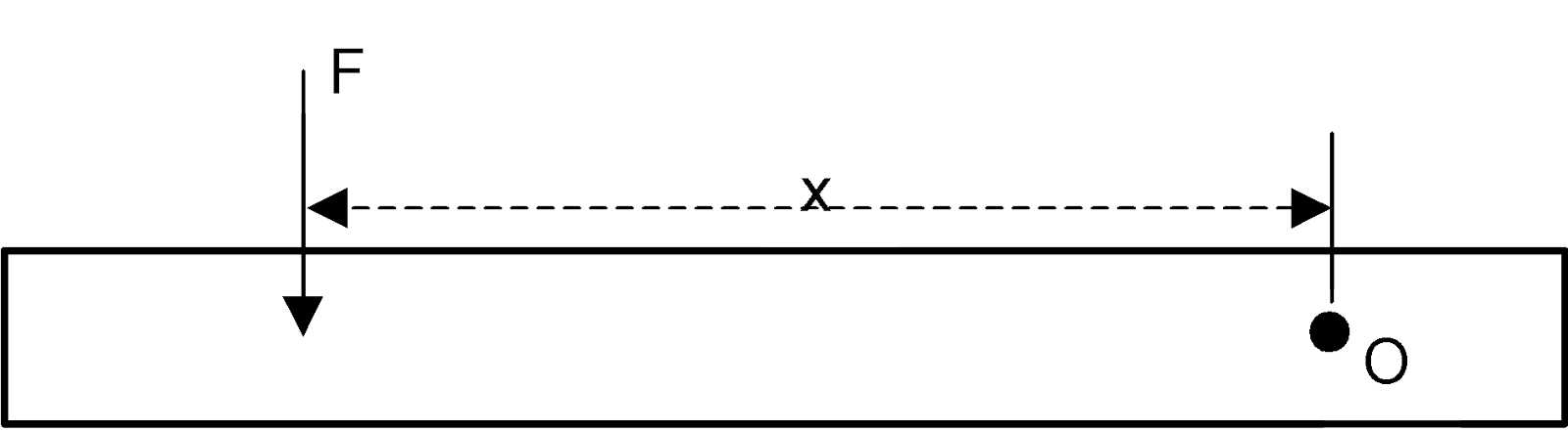
The diagram shows Moment of F about O = Fx anticlockwise. The units of a moment are Nm, and a moment is sometimes called a torque, T.
Couple
The moment produced by two equal and opposite parallel forces that don’t act in the same straight line is called a couple. The moment produced by a couple is equal to the product of one of the forces and perpendicular distance between their lines of action.
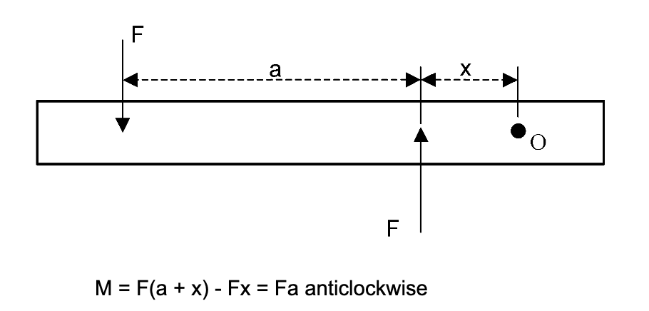
The moment is independent of the distance, X, and is the same about any point in the same plane. In the image below we can see a wrench. The use of the wrench applies a force, F, at a perpendicular distance from the turning point. In this case the turning point is the centre of the nut. The turning moment, or torque, applied is force x perpendicular distance.
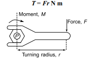
Let’s check out an example to see how this can work. Imagine a pulley wheel with a diameter of 500mm. It has a force of 1000N applied at the rim, and we’re going to work out the torque when this happens.
Torque T = Fr, where force F = 100N and radius r =500/ 2 = 250 mm = 0.25m.
Hence, torque, T = (100)(0.25) = 25 Nm
Sum of Moments
When several forces are lying in the same plane and act on a body, the moments about any point can be added. We need to take into account the sense of rotation for each moment. Imagine that forces of magnitude three end, 4 N and 5 N are applied to a beam of length 6 metres as shown in the diagram:
Moments about point A, clockwise, can be taken as:
- Moment of the 3N force about A is: 3×0 = 0Nm
- Moment of the 4N force about A is: 4×4=16Nm anti-clockwise (ACW) so -16Nm
- Moment of the 5N force about A is: 5×6=30 Nm CW so +30Nm
The Total Moment about point A = -16+30 = +14Nm (CW)
Keep an eye out for our next articles looking into how fluids and heat can affect engineering problems.
Interested in our courses?
You can read more about our selection of accredited online mechanical, electrical, civil and aerospace engineering courses here.
Check out individual courses pages below:
Diploma in Electrical and Electronic Engineering
Higher International Certificate in Electrical and Electronic Engineering
Diploma in Electrical Technology
Diploma in Renewable Energy (Electrical)
Higher International Diploma in Electrical and Electronic Engineering
Diploma in Sustainable Construction
Diploma in Structural Engineering
Diploma in Building and Construction Engineering
Higher International Certificate in Civil Engineering
Higher International Diploma in Civil Engineering
Diploma in Aerospace Structures
Diploma in Principles of Flight
Diploma in Aerodynamics, Propulsion and Space
Higher International Diploma in Mechanical Engineering
Higher International Certificate in Mechanical Engineering
Diploma in Mechanical Engineering
Diploma in Mechanical Technology
Alternatively, you can view all our online engineering courses here.
Recent Posts
Types of Aircraft Drag Explained: Induced, Profile and Interference Drag
Types of Aircraft Drag Explained: Induced, Profile and Interference Drag An aircraft experiences several forms of aerodynamic drag at the same time. Some result from generating lift, some arise as air flows over the aircraft’s surfaces, and others are created when airflow around neighbouring components interacts. For a conventional aircraft in subsonic flight, total drag […]
Induced Drag Explained: Why Flying Slower Can Increase Drag
Induced Drag Explained: Why Flying Slower Can Increase Drag Why can an aircraft experience more drag when it flies more slowly? We usually associate greater speed with greater air resistance, but a wing must also generate enough lift to support the aircraft. Induced drag is the drag associated with producing lift on a finite-span wing. […]
Laminar vs Turbulent Boundary Layers: Why Airflow Separates from Aircraft Wings
Laminar vs Turbulent Boundary Layers: Why Airflow Separates from Aircraft Wings Airflow around an aircraft wing is often shown as smooth streamlines passing neatly over the aerofoil. In reality, the thin layer of air immediately next to the wing surface behaves very differently from the undisturbed airflow further away. This region is called the boundary […]